Hej!
Tak na szybko znalazłem w jakich swoich starych archiwach:
Oczywiście poszukam jeszcze, jak coś znajdę będę dorzucał w tym wątku.
Nie jesteś zalogowany. Proszę się zalogować lub zarejestrować.
Drwal 1.3 od Larka Nowa wersja gry Drwal przynosi poprawki w algorytmach i balansie rozgrywki.
FujiGPT - klient LLM dla Atari XL/XE FujiGPT pozwala na rozmowę z modelami językowymi na klasycznych ośmiobitowych komputerach Atari.
ABBUC Creative i Application Contest Poznaliśmy oficjalne wyniki konkursów Creative oraz Application Contest organizowanych przez ABBUC.
Echa Sommarhack 2026 Zakończył się szwedzki zlot Sommarhack 2026. Dead Hackers Society zachwyca nowym demem na Atari STE.
TURGEN 9.4.4 Nowa wersja narzędzia TURGEN naprawia błędy w obsłudze wiersza poleceń.
atari.area forum » Posty przez seban
Hej!
Tak na szybko znalazłem w jakich swoich starych archiwach:
Oczywiście poszukam jeszcze, jak coś znajdę będę dorzucał w tym wątku.
Hej!
by było śmieszniej - nazywał się Mirosław Liminowicz, ale to tylko zbieżność nazwisk, o ile wiem ;)
A to ten człowiek o którym mówię to na pewno kto inny. W sobotę urzędował co prawda na Grzybowskiej (coś mętnie kojarzą że niedaleko stanowiska K.Steca, gdzieś po prawej stronie stojąc twarzą do stanowiska Krzysztofa. W niedzielę natomiast miał stoisko na Saskiej 78 (dawne warszawskie technikum chemiczne) ... praktycznie prawie prosto na przeciwko wejścia na korytarz na parterze, i właśnie tam mi zamontował KSO Turbo 2000 i tam też jeździłem w niedzielę na "stuff", nagrywał on kasety na miejscu, ale było o wiele spokojniej niż na Grzybowskiej, można powiedzieć ze było tam bardziej kameralnie, po pewnym czasie znałem tam sporo ludzi, całkiem fajnie towarzystwo tam się zbierało, w sensie że nie tylko handlarzy ale również wymieniających się wiedzą i doświadczeniem, pamiętam że poznałem tam kolegów spectrum-owców i to dzięki nim i ich wiedzy i tłumaczeniom napisałem program do ładowania plików z ZX Spectrum przy pomocy XC12 z zamontowanym Turbo2000F... program służył potem głownie jako narzędzie do przenoszenie obrazków z ZX-a... a koledzy od spectruma nagrywali mi te pliki/gry/obrazki jak szaleni ... pamiętam to całe towarzystwo jako grupę entuzjastów informatyki, programowania i w tamtym czasie jako źródło wiedzy wszelakiej :) a byłem wtedy naprawdę młodym człowiekiem i niewiele wiedziałem, ale oni chętnie tłumaczyli cierpliwe wszystko dokładnie takiemu leszczowi jak ja :)
Jeszcze wracając do tego człowieka który montował mi turbo... coś mi się kołacze po głowie że mógł mieć ksywkę "Czar Soft"? Może się mylę... może to zupełnie ktoś inny był, ale wybaczcie.. to było tyle lat temu, że wspomnienia się zacierają.
Hej!
Dzięki QTZ za linki, opis i przypomnienie wątków z AoL! Zupełnie o nich zapomniałem faktycznie udostępniłem tam również to co znalazłem wcześniej u siebie, leżało na serwerze slight (i nadal tam leży, tylko dostęp do listy plików został wyłączony po migracji na inny serwer WWW). Postaram się to poprawić, ew. przeniosę do katalogu na pigwie. Dobrze że zrobiłeś "mirror" i udostępniłeś bezpośrednio. Dzięki!
Co do wtyczki i interface, wygląda na to że mamy "turbo KSO" od tego samego człowieka, Brazylijska jak i również jednakowe ustawienie głowicy też się zgadza. Jak odwiedzę kiedyś piwnicę u mojej mamy w bloku, to tam pewnie jest mój magnet jeszcze to zrobię foty tego co jeszcze z niego zostało (na pewno nie ma klapki :P) ale sam interface, cart i magnetofon jeszcze mam nadzieję istnieją (o ile myszy czy inne cholerstwo tego nie zeżarły)
Odgrażam się kolejny raz, ale w końcu będę musiał temat "Turbo KSO 2000" ogarnąć i zrobić w końcu jakiś sensowny i uniwersalny handler do tego, bo jak popatrzyłem na ten mój "wytwór" który udostępniłem w swojej "paczce" to mi słabo, co prawda ładuje się pod ROM, ale po pierwsze obsługuje Turbo 2000F, a po drugie to w jaki sposób umieszcza wpis w tablicy HTABS jest tak lamerskie że nie wierzę że coś takiego mogłem popełnić :D no ale wtedy działo, nie zastanawiałem się czy tak można, czy wypada, czy zgodne ze sztuką... :) można powiedzieć że to "dirty hack łatany dirty hackiem" ;D
Przy dobrze zrobionym SIO2PC nie powinno być żadnego problemu w równoległej pracy magnetu z KSO Turbo 2000 i samego SIO2PC.
Oooo!! :) A nadal planujesz opisywanie moich magnetofonów? I jak na dziś byś szacował termin odesłania? Możesz odpisać na priv :)
Jak najbardziej planuję dokończyć tę sprawę, nawet wspominałem o tym w wątku o SlightSID że aktualnie sprawa Twojego sprzętu ma priorytet i obecnie jest właśnie na tapecie, nie chcę podawać jakichś konkretnych terminów... bo obecna sytuacja w kraju i na świecie jest cholernie poważna, a członkowie mojej rodziny (szczególnie jedna osoba, o czym Ci pisałem na prawie rok temu na priv) są w grupie ryzyka naprawdę nie wiem co się stanie, trudno więc podejmować jakieś terminowe zobowiązania.
Opisy magnetów z ciekawymi "środkami" będą lodowały w tym wątku jak już niejednokrotnie się zarzekałem, mam nadzieję że wkrótce będą widoczne efekty w tym wątku.
A jeszcze jedno mi się przypomniało, wspominany już niejednokrotnie W. Zabołotny oprócz Autocopy napisał program "Kopiarka Dysk<>Turbotape":
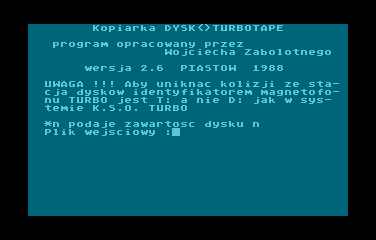
Ten program załadowany z poziomu DOS-a instaluje również handler "T:" w systemie i umożliwia przenoszenie programów pomiędzy stacją dysków a magnetofonem wyposażonym w "Turbo KSO 2000", link do programu:
EDIT: właśnie się zorientowałem iż ów program znajduje się również na dysku który udostępnił Jer na swojej stronie (link w postach wyżej).
EDITED@2025.08.13: http to https links updated.
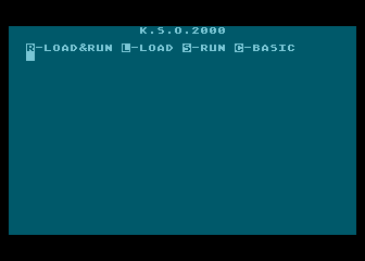
Dobra, teraz rozumiem ;) Ta binarka którą udostępniłem to jest .XEX który ładuje się zamiast cartridge, po prostu zamiast cart-a uruchamiasz .XEX który jest spreparowany że jego uruchomienie jest tożsame z tym gdybyś uruchomił samego carta.
Jeżeli chcesz kopiować coś dysk ---> taśma, to tak jak pisałem zostaje Ci załadowanie z DOS-a handlera instalującego urządzenie "T:" w systemie, lub skorzystanie z kopiarki o której pisał Jer i która jest udostępniona na jego stronie:
dereatari ---> serwis ---> Turbo KSO, na tej stronie Jer-a jest również link do wspominanej dyskietki: Dysk Turbo 2000
EDITED@2025.08.13: links to JER pages updated.
W jakim sensie obsługa stacji dyskietek?
Jeżeli chcesz kopiować dysk -> taśma, to tak jak pisał Jer musisz użyć programu kopiującego obsługującego Turbo2000 ładowanego z poziomu DOS (np. wspominane AutoCopy, bo były też tzw. handlery "T:", czyli programy rezydentne które instalowały w systemie urządzenie "T:" i dzięki temu można było kopiować dysk <---> turbo2000 przy pomocy dowolnego programu kopiującego lub nawet polecenia "Copy File" z poziomu DUP.SYS czy "command line" (w zależności od używanego DOS-a). Handler "T:" dla systemów serii Turbo 2000 (KSO oraz F) nawet kiedyś popełniłem (bardzo dawno temu) i chyba go gdzieś udostępniałem, poszukam... jak znajdę wrzucę tu.
Jeżeli mówisz o używaniu stacji przy włożonym carcie, jest to właściwie niewykonalne (może lepiej napisać iż niepraktyczne) bo cart instaluje w systemie urządzenie "D:", więc brak miejsca i możliwości klasycznej obsługi stacji dysków, chyba że ktoś sobie napisze program który będzie ładowany z poziomu Turbo i będzie używał bezpośredniego dostępu do stacji dysków przez SIO (takie programy też były).
Należy pamiętać że jak ktoś instalował sobie Turbo2000 to na pewno nie miał w 90% przypadków żadnej stacji dysków (a jedynie magnetofon), więc tego rodzaju narzędziami (współpracującymi zarówno ze stacją jak i turbo) dysponowali raczej handlarze giełdowi, którzy to nagrywali gry/programy swoim klientom na kasety. Chronili ten soft, bo to był ich sposób na zarobek .... więc ograniczali jego dostępność jak mogli. Przynajmniej tak to wyglądało z moich obserwacji tego co się działo na Grzybowskiej, Saskiej czy na giełdzie komputerowej w stodole.
Oczywiście należy brać pod uwagę że to moje spojrzenie na sytuację wtedy panującą, może to być oczywiście obraz wypaczony bo byłem wtedy naprawdę młodym człowiekiem i to było obraz który zapamiętałem gdy wtedy kręciłem się po giełdach w poszukiwaniu, wiedzy, softu, literatury.
Jak teraz się patrzy np. na inne systemy turbo, np. Blizzarda, widać że ludzie zajmujący się Blizzardem (inny region Polski) mieli zupełnie inną politykę, udostępniali narzędzia i starali się robić soft i sprzedawać swoje dzieła np. w formie cartów. Nie wiem czy to wrażenie które odnoszę nie jest mylne, ale jak patrzę na dostępność softu Blizzard vs Turbo 2000 to Blizzard może się pochwalić o wiele bogatszą bazą dostępnego oprogramowania, a także lepszą jakością tegoż softu. W przypadku Turbo KSO 2000 to mam wrażenie że większość bazowała na tym czego dokonał W. Zabołotny.
Hej!
Na 99% to KSO Turbo 2000, nie mam co prawda Ultimate Cart-a, ale widzę że on emuluje wiele innych cartów, więc da się przygotować dla niego na pewno jakiś obraz który będzie zawiera soft dla KSO Turbo 2000, nie powinno być z tym większego problemu, rzucę okiem na dokumentacje do tego carta i dam jeszcze znać.
Z tego co na szybko wyczytałem widzę że Ultimate Cart potrafi uruchamiać pliki .XEX, jeżeli tak to jak wrócę do domu to poszukam plików, ale gdzieś, kiedyś już chyba wystawiałem oprogramowanie do KSO Turbo 2000 w formacie .XEX.
EDIT#1: Chyba znalazłem: to jest to co miałem na carcie który dostałem z moją wersją Turbo KSO 2000, którą zamontowano mi na giełdzie komputerowej w technikum chemicznym na ul. Saskiej w Warszawie. Cart gdzieś jeszcze mam, jak odkopię to wrzucę do tego wątku oczywiście, ale na chwilę obecną mam tylko wersję XEX: Turbo KSO 2000.xex
EDIT#2: Jeżeli chodzi o instrukcję to widzę że ktoś (ERD/Retroreaders) przesłał materiały które zostały umieszone na AoL:
K.S.O. Turbo 2000 - do samodzielnego montażu <--- pierwsze strony to dość dokłada instrukcja.
EDITED@2025.08.13: http to https links updated.
Hej!
Dzięki za foty! Czyli wiadomo już że ten cart to "oryginał" tegoż klona: Turbo2000 COPY (a tak naprawdę Turbo 2T12).
Swoją drogą ciekawe że Atrax wziął rozwiązanie Wojciecha Zabołotnego i je po prostu sprzedawał. Czasy były takie że pewnie żadnej umowy nie mieli ;) ... i właśnie dlatego ująłem słowo "oryginał" w cudzysłowy. Ja pierwszy raz z tym rozwiązaniem (Turbo 2T06) zetknąłem się czytając IKS-a w tamtych czasach.
Sądzę że późniejsze KSO Turbo 2000 to był hack/modyfikacja właśnie Turbo 2T12 czy 2T06 od W.Zabołotnego. kiedyś usiądę i porównam kod, pewnie się nie raz zdziwię.
No i jeszcze raz dzięki za podzielenie się zdjęciami carta, dowiedzieliśmy się czegoś nowego :) uwielbiam takie wykopaliska! :)
Hej!
Czyli PCB jest identyczne z: Turbo 2000F Copy również od Atrax.
Pytanie co zawiera pamięć EPROM w Twoim carcie? Zastanawiam się, bo Atrax miał w zwyczaju pisać "Turbo 2000 KSO" zarówno na carty z oprogramowaniem dla KSO Turbo 2000 jak i dla Turbo 2000F. Gdybyś wrzucić zdjęcie/screen z uruchomionym cartem można by zobaczyć czy to soft dla KSO Turbo 2000 czy dla Turbo 2000F (o ile będzie to standardowy soft).
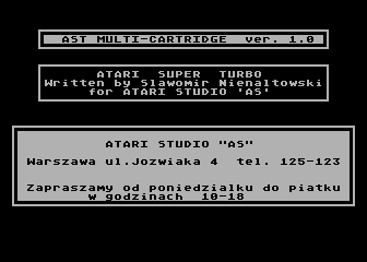
I do kompletu AST Multicartridge od VLX-a... o ile pisałem już tym carcie we wcześniejszym wątku/poście: AST Multicartridge, to warto również zaprezentować wersję posiadaną przez VLX-a, ponieważ jest to wersja wcześniejsza, oznaczona numerem wersji 1.0, co widać po uruchomieniu carta i wybraniu opcji "J":
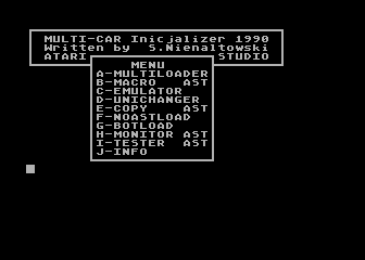
Opisywany w poprzednim wątku Multicart był natomiast oznaczony wersją 2B: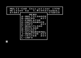

Nie przedłużając więcej wywodu na temat różnic w cartach, podsumuję to może w tym poście zbierając wszystko w jednym miejscu, zatem do pobrania mamy:
schemat, wersja wektorowa identyczny dla obu wersji cartridge.
zawartość pamięci EPROM wersji 1.0
zawartość pamięci EPROM wersji 2.B
sumy SHA256 plików z zawartością EPROM:
0fa3d7a1d0441a1f48f11863d69909f75a38e29927518a26fbd0609386806893  ast_multicartridge_v1.0.bin
8f2964542f776308013e9c8e0191e76424e0e926a4990a375ffe5e2f7f75234a  AST_multi_cartridge.bin
i na sam koniec, zdjęcia:
AST Mulricartridge 1.0: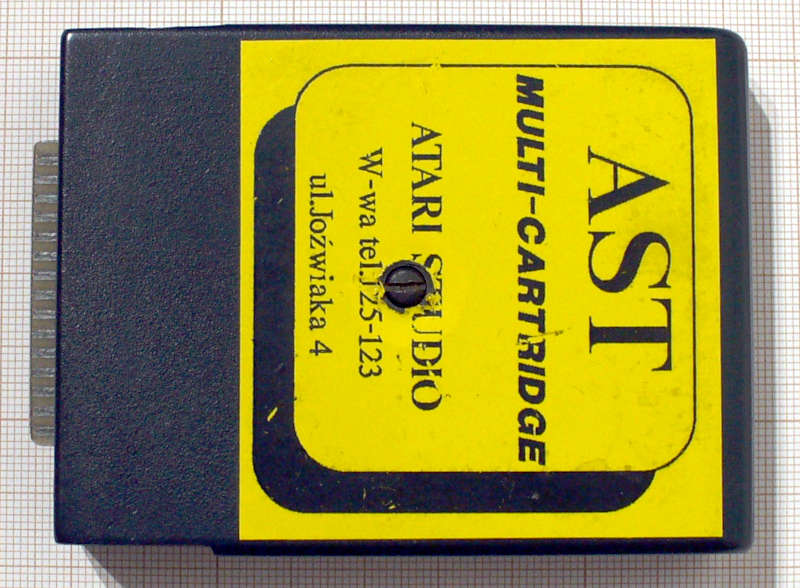
płyta drukowana góra: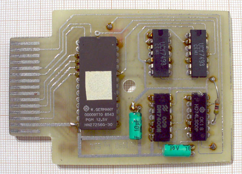
płyta drukowana dół: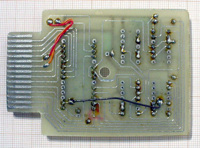
EDITED@2025.08.13: http to https links updated.
No dokładnie :) pewnie wyprowadzenie przez otwory montażowe nie chciały przejść, to ktoś zrobił sobie z tego "SMD" i zamontował od drugiej strony odpowiednio podginając/profilując wyprowadzenia.
W tym poście krótko i zwięźle opisane będą carty dla systemu KSO Turbo 2000. Dwa carty które dostarczył VLX mają identyczny schemat, a także identyczną zawartość pamięci EPROM. Pamięć EPROM o pojemności 2KB (typ 2716 lub jej sowiecki odpowiednik) mapowana jest standardowo w obszar $A000-$BFFF (zawartość 2KB pamięci EPROM powtórzona jest w tym 8KB obszarze 4 razy).
Po starcie cart przepisuje zawartość EPROM w niższy obszar pamięci, a następnie przechodząc pod nowy adres, monitoruje stan linii TRIG3 która informuje czy cart jest jeszcze aktywny czy już nie (kopia staniu linii RD5 w złączu cartridge), w ten sposób czeka na zadziałanie układu czasowego. Odłączenie carta jest realizowane przez już wspomniany prosty układ czasowy RC złożony z kondensatora, rezystora oraz dwóch tranzystorów PNP. Gdy kondensator naładuje się, do poziomu w którym tranzystory Q1, Q2 przestaną przewodzić i linia RD5 zostaje dezaktywowana (stan niski), software przechodzi do dalszego działania.
W tym poście krótko i zwięźle opisane będą carty dla systemu KSO Turbo 2000. Dwa carty które dostarczył VLX mają identyczny schemat, a także identyczną zawartość pamięci EPROM. Pamięć EPROM o pojemności 2KB (typ 2716 lub jej rosyjski odpowiednik) mapowana jest standardowo w obszar $A000-$BFFF (zawartość 2KB pamięci EPROM powtórzona jest w tym 8KB obszarze 4 razy).
Po starcie cart przepisuje zawartość EPROM w niższy obszar pamięci, a następnie przechodząc pod nowy adres, monitoruje stan linii TRIG3 która informuje czy cart jest jeszcze aktywny czy już nie (kopia staniu linii RD5 w złączu cartridge), w ten sposób czeka na zadziałanie układu czasowego. Odłączenie carta jest realizowane przez już wspomniany prosty układ czasowy RC złożony z kondensatora, rezystora oraz dwóch tranzystorów PNP. Gdy kondensator naładuje się, do poziomu w którym tranzystory Q1, Q2 przestaną przewodzić i linia RD5 zostaje dezaktywowana (stan niski), software przechodzi do dalszego działania.
Schemat to standard z tamtych czasów, cart od Atrax na standardowe wartości i typy elementów , możemy nazwać to konstrukcją referencyjną ;) (rezystory 100K, kondensator 22uF, tranzystory BC308, dioda 1N4148). W karcie "klonie" rezystory o mniejszej wartości, kondensator 10uF i polska dioda (prawdopodobnie BAVP21) zamiast 1N4148, jednak znaczenie tego jest marginalne.
Do pobrania:
schemat - wersja wektorowa PDF
KSO2000_atrax.zip
KSO2000_clone.zip
Oba pliki zip z zawartością pamięci EPROM obu cartów są oczywiście identyczne, ale wrzucam dla porządku to co zgrałem z tych kostek aby nie było wątpliwości że są jakieś różnice.
sumy SHA256 obu plików:
03d1c0d28f7dd2fc71a19bff17fc8d0638fdefbcec51813476a5637453c2d0aa  kso2000_atrax.bin
03d1c0d28f7dd2fc71a19bff17fc8d0638fdefbcec51813476a5637453c2d0aa  kso2000_clone.bin
Oczywiście podziękowania dla VLX-a oraz Duddie-go za udostępnienie cartów, a na zakończenie wygląd cartów i ich wnętrza:
Cartridge KSO 2000 od Atrax: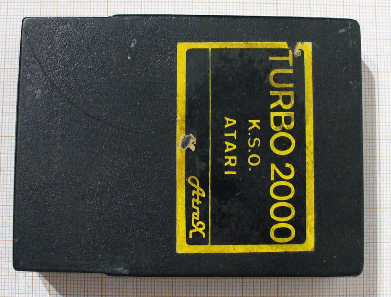
płytka drukowana góra: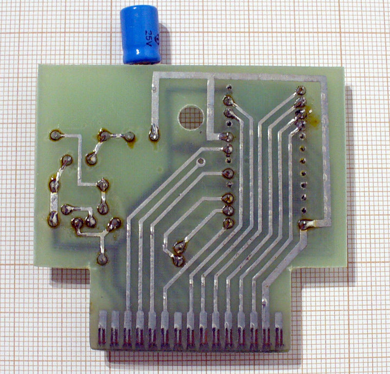
płytka drukowana dół: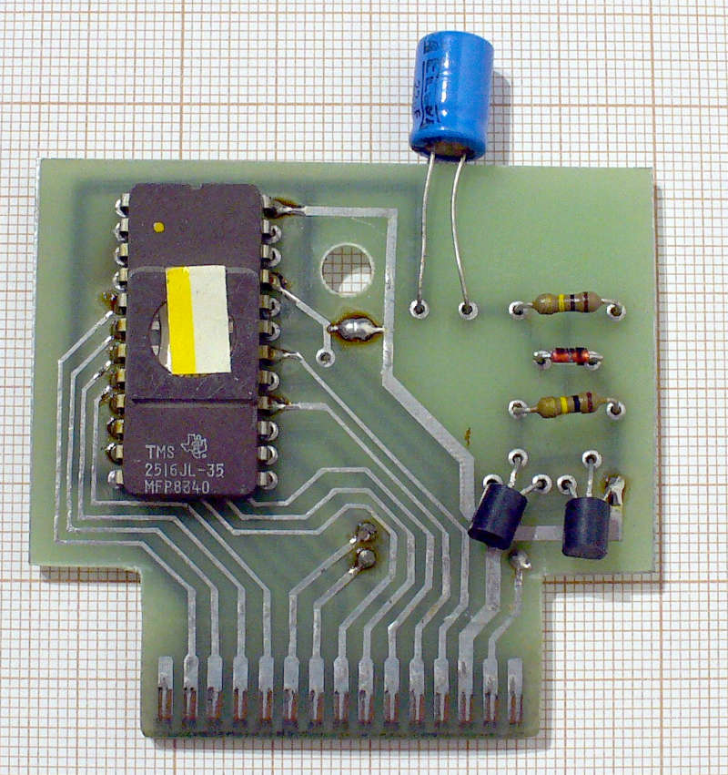
Cartridge KSO 2000 giełdowy/domowy klon: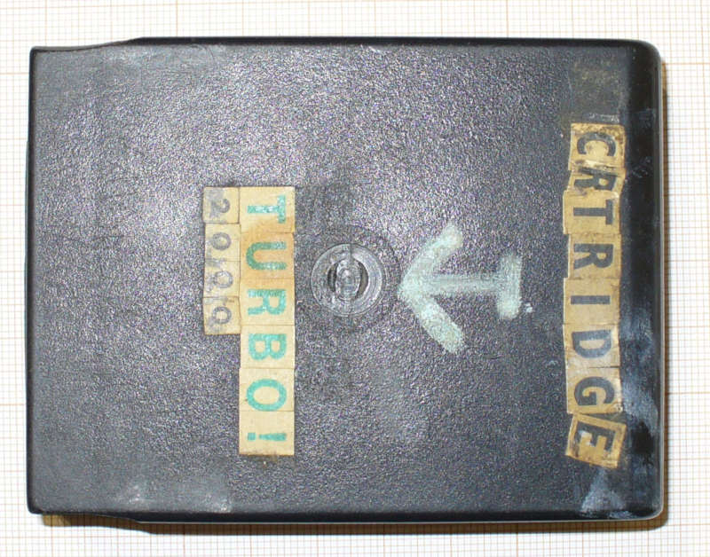
płytka drukowana góra: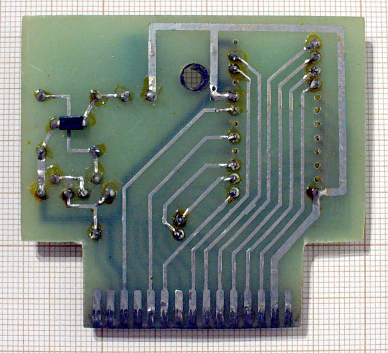
płytka drukowana dół: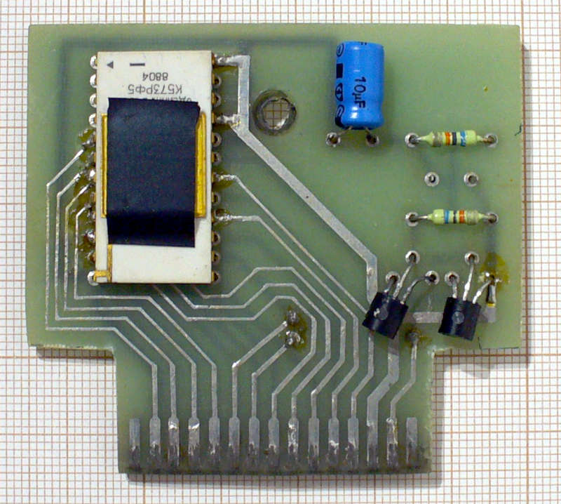
EDITED@2025.08.13: http to https links updated.
Dzień dobry!
Po dłuższej przerwie, w ramach ogarniania spraw zaległych chciałem wrzucić dumpy kolejnych cartów które wpadły w moje ręce. Carty przekazał VLX w ręce Duddiego... i trafiły one do mnie w celu wykonania analizy i dokumentacji, nie będą to jakieś super "nowości", jednak w ramach projektu "archiwizacji dla potomnych" wrzucę każdą wersję która wpadnie w moje ręce ;)
Zgodnie z tym co przekazał mi Duddie, VLX przekazał 3 cartridge a były to:
1 szt) AST-Multicartridge
2 szt) KSO 2000 Turbo Cartridge (jeden cart do wyrób firmy Atrax, drugi to jakiś giełdowy/domowy klon)
W dniu dzisiejszym wrzucę w kolejnych postach poniżej zdjęcia, schematy, zawartość EPROM tychże kartów.
No to jeżeli głównym kryterium jest cena oraz do kompletu rozmiar, to na szybko możesz spróbować również totalnej chińszczyzny (BCD Semiconductor które jest pod "skrzydłami" Diodes, INC.) czyli AP3012, taniej w PL chyba się chyba kupić nic nie da ;-)
Ale jak mówię nie przeprowadzałem jakiś dużych testów, będziesz musiał poeksperymentować sam :) Układ jak TS1935 czy MCP ma zintegrowany tranzystor kluczujący, pracuje wysoko bo również na 1.5MHz, a więc łatwe filtrowanie zasilania, i mała wymagana przy taj częstotliwości kluczowania indukcyjność. Może Ci się sprawdzi w Twoich zastosowaniach.
Ja bardziej szukałem na ebayu i na aliexpress - nie widzę TS1935B, a MCP1661T owszem jest, ale nie w "chińskiej" cenie :)
mówisz że chcesz w chińskiej cenie... no też są: https://lcsc.com/product-detail/DC-DC-C ... 26188.html
tylko czy ja bym chciał mieć podłączonego do tego SID(y) wartego sto/dwieście razy tyle? ;) no nie wiem czy bym chciał ryzykować... nie mam żadnych danych dotyczących żywotności ani zachowania tych przetwornic w różnych warunkach... z przetwornicami od TS czy MCP trochę wojowałem i nie miałem negatywnych doświadczeń... z przetwornicami za taką cenę nie walczyłem zbyt długo... projekty w których używałem tego typu rozwiązań były zbyt ważne aby ryzykować aż takie oszczędności.
Są i tańsze rozwiązania od MCP1661T, (nawet w TME), ale jak mówię nie jestem pewien ich zachowania i stabilności w dłuższym okresie czasu, więc nie chcę polecać nic czego nie jestem pewien.
Z takich których jeszcze używałem są dawne MIC2288 produkowane przez Micrel-a (obecnie kupionego przez Microchipa :P).
Układów tego typu są naprawdę dziesiątki, producentów pewnie również kilkudziesięciu... jak chcemy za step-up zapłacić np. 30 groszy to można zejść nawet do 34063, tylko komponenty do filtrowania zasilania z tego typu przetwornicy zajmą sporo miejsca i będą kosztowały więcej niż sama przetwornica, już zresztą pisałem o tym nie raz... bo przez to też przechodziłem:
*) lewy dolny róg ;-)
Ja odpowiem równie krótko... masz 100% racji... po prostu działajmy!
Jeszcze dwa słowa o magazynie dyskowym Barymag... to nie tylko dzieło ludzi ze Slight, magazyn powstał bo dużo ludzi nam w tym pomogło, dużo artów pisali bardzo wartościowi ludzie z ówczesnej sceny... właściwie to dużo na głowę wziął P.W. i to on pilnował wszystkiego, my jedynie dorzuciliśmy swoje 3 grosze, a więc trochę kodu, trochę artów, trochę muzyki... szkoda tylko, że nie udało się więcej numerów stworzyć. Z perspektywy czasu, jak się to teraz czyta to można się nieźle uśmiać bo byliśmy wtedy naprawdę młodzi i niejednokrotnie pełni buty i zarozumiali, wręcz przekonani o swojej nieomylności... ale wiesz grzechy młodości :D Ale mimo wszystko uważam że warto było... to był świetnie spędzony czas! Bawiliśmy się doskonale... myśleliśmy że możemy wszystko :) a teraz im dłużej się chodzi po tej ziemi tym ma się wrażenie że wiedzy coraz więcej do opanowania, a czasu coraz mniej :)
Oprócz Barymag#1 z 1994 roku, był jeszcze Barymag#2 z 1996 roku... oczywiście wrzucimy go na www również, ale obecnie niestety dostępny jest tylko w formie 4 plików ATR... np. na Demozoo lub bezpośrednio ze slight.pl -> Barymag #2.
Ale to chwilę potrwa bo w kolejce mam jeszcze sprzęt od uicr0bee który trzymam tyle czasu że aż wstyd i to on obecnie ma priorytet, jak zakończę przegląd tego i odeślę paczki to przyjdzie i pora na Barymaga i na resztę projektów :) Właśnie dlatego w końcu chciałem zakończyć już temat SlightSID-a i zrobić release, bo wisi on nade mną jak przysłowiowy miecz Damoklesa ;) Zawsze tam gdzieś z tyłu głowy siedział i upominał się o zakończenie, tylko ostatnie lata przyniosły parę niestety wrednych sytuacji życiowych, które wszystko dodatkowo opóźniły.
Hej!
ja kupowałem na początku w Farnell (jak jeszcze nie był wykupiony przez Avnet i był oficjalnym dystrybutorem Tawian Semiconductor), a potem kupowałem bezpośrednio z chin. Układy TS1935B są cały czas produkowane, ale jeżeli obecnie jest problem z dostępnością w PL to można oczywiście użyć innych układów, każdy z producentów ma coś zgodnego pin-owo w swojej ofercie, chociażby MCP1661T od microchip-a. Są dostępne "od ręki" w TME.
Należy pamiętać aby w przypadku zastosowania tegoż układu, dostosować dzielnik (R14,R17) od sprzężenia zwrotnego, bo widzę że Vfb dla MCP1661T jest trochę niższe niż w przypadku TS1935B.
@sebanOczywiście, że Twoja dłubanina interesuje :) Kilka osób z pewnością skorzysta z Twojej wiedzy i doświadczeń.
Dzięki za miłe słowa! Moja wiedza i doświadczenie nie jest jakieś wielkie może, ale nawet gdy z tego będzie mogła skorzystać jedna osoba, będzie mi niezmiernie miło.
Co do dzielenia się wiedzą i pomysłami w celach niehandlowych - zawsze mówiłem i mówił będę, że postęp bierze się nie z konkurencji, a ze współdziałania i wolnego udostępniania wszelkiej wiedzy. Ileż razy widząc coś wymyślonego przez innych zdarzało się powiedzieć: Kurde - jakie to proste... I świat idzie do przodu.
Świetnie powiedziane, zgadzam się z tym w 100%. Dobrze że w tych szalonych nieco czasach są jeszcze tacy ludzi jak Ty czy np. Tebe który robi świetną robotę w dzieleniu się wiedzą, kodem, etc. Jest oczywiście cała masa innych ludzi którzy dzielą się swoją wiedzą i udostępniają kod i projekty... nie sposób ich tu wszystkich wymienić, ale np. Tebe nawinął mi się pod klawisze ponieważ jakoś skojarzyłem jego wątek o efektach, jego kompilatory, oraz całą masę softu wychodzącą z pod jego ręki... i to wszystko ten człowiek udostępnia publicznie i całkiem za darmo! Tak myślę że, aby uratować tą naszą kurczącą się scenę potrzeba właśnie takich ludzi jak Wy, którzy pozwolą innym poznać i nauczyć się co i jak jest robione... na scenie posucha, bo nikt już nie pamięta jak robić jakieś efekty... została garstka "mistrzów Zen", których kod zadziwia ... jednak jak to się mówi koszt wejścia "nowych", w ten temat jest duży... bo mało jest prostych przykładów, od razu należy zaczynać z "grubej rury", a to czasami nie jest takie proste i oczywiste... ale na ten temat też coś się poradzi... szkoda że czasu tylko mało tak! :)
Co do projektów i www. Pozostały już tylko większe porządki i zabudowa otoczenia naszego nowego domu co oznacza, że powinno być więcej ciekawostek dla Atari i może nie tylko. Potrzebuję na to po prostu więcej czasu, o czym Ty doskonale wiesz, bo masz podobny problem - doba jest zdecydowanie za krótka.
No to trzymam kciuki za dokończenie tak ważnej inwestycji! Doskonale rozumiem jaki to wysiłek i jak dużo czasu pochłania. Oczywiście doba jest za krótka, zgadzam się! :)
Wracając do SlightSID - rozumiem dlaczego zastosowałeś taką konstrukcję odnośnie rejestrów do odczytu. Kiedyś to wyjaśniałem w związku z moim rozwiązaniem interfejsu SID. Logika nie da rady "skoczyć" w przyszłość. Zawsze dane muszą być wcześniej przygotowane. Ty robisz to poprzez wpis do rejestru indeksowego. Ja mam leżący od lat pomysł, w którym SID jest w czasie "bezczynności" odpytywany z zawartości rejestrów RO - OSC3, ENV3. Dane z rejestrów są na bieżąco wpisywane do czterech rejestrów pośrednich, które są widoczne z poziomu Atari jak zwykłe rejestry SIDa, które można po prostu odczytać. Wartości z tych rejestrów są po prostu próbkowane tak często jak się da.
Przyznaję że jest to bardzo ciekawe podejście! :) Moje myślenie nigdy nie podążyło tymi ścieżkami! To właśnie pokazuje jak fajnie jest dzielenie się pomysłami, swobodna wymiana myśli i pomysłów to coś pięknego! Właśnie udowodniłeś empirycznie że to o czym piszesz działa :] Po prostu niesamowite jak szybko się to sprawdziło. Chodzi mi o to że jak tematem zajmuje się kilka osób to każdy wymyśla swoją ścieżkę postępowania i o ile ileś osób wymyśli sobie coś podobnego, to znajdzie się zawsze ktoś kto podąży inną ścieżką.
Jedno mnie tylko zastanawia w tym rozwiązaniu - czy SID się nie przegrzeje od ciągłego zapisywania/odczytywania :D
O to bym się nie obawiał :) W końcu te układy były projektowane w standardowy sposób :) Zapis/Odczyt to dla nich chleb powszedni ;) Przyznam natomiast że ja się zafiksowałem jakoś na "jakości" sygnału wychodzącego z SID-a, wymyśliłem sobie jakieś "low-noise" wzmacniacze operacyjne, przetwornicę step-up pracującą dość wysoko (częstotliwość przełączania TS1935B to około 1.2MHz, przy tej częstotliwości kluczowanie dość łatwo filtrować zasilanie). Pierwsze wersje SlightSID bazowały na starym poczciwym MC34063 pracującym dość nisko, ale to też się dało odfiltrować, tylko zajmowało dużo miejsca ;) bo duże pojemności, duże indukcyjności filtrujące, etc. ... no więc to moje zafiksowanie się na minimalizacji szumu, spowodowało ze chciałem też do minimum ograniczyć ilość odwołań do układu SID, bo każdy zapis/odczyt przez CPU to teoretyczne przełączenie jakiejś tam ilości logiki w strukturze układu, ale takie myślenie jak widzisz założyło mi jakieś klapki na oczy :) nawet nie pomyślałem aby odczyt rozwiązać w sposób jaki zaproponowałeś... a to też jest ciekawe podejście!
Wrzucam schemat. Może komuś się spodoba. Wygląda na to, że powinno wszystko dać się upchnąć do jakiegoś xilinxa. Niestety - dotychczas nie miałem kiedy siąść do prototypowania układu. Mam częściowo złożony na dużej uniwersalnej pcb układ lutowany kynarem ale chyba dam z tym spokój i w przyszłości spróbuję ogarnąć to na XC95144XL a może i na mniejszym? Układ może mieć błędy uniemożliwiające działanie, dlatego ostrzegam - to tylko taka wrzutka poglądowa a nie gotowiec do budowy docelowego urządzenia.
Fajnie że podzieliłeś się już teraz na wczesnym etapie swoim pomysłem, wiedzą i wstępną realizacją. Przyznaję że podziwiam cierpliwość że chciało Ci się jeszcze w dzisiejszych czasach robić to wszystko "na piechotę". Moje lenistwo pchęło mnie właśnie w stronę CPLD chociaż przyznaję, że lubię też realizować wszystko właśnie na ową "przysłowiową" piechotę, lub na drodze software-owej... ale to pewnie zauważycie przy udostępnianiu kolejnych projektów.
Jeśli siądę kiedyś do tego (czekają jeszcze w kolejce 3 spore projekty) chętnie skorzystam z Twoich rozwiązań odnośnie zasilania układu i ogarnięcia wyjść audio bo tego mi brakowało - kto by chciał zniszczyć oryginalnego SIDa? Myślę, że i dodanie wyboru PAL/NTSC też byłoby pożądane, nie?
Przyznam że z niecierpliwością czekam na każdy Twój release... lubię czytać, oglądać i analizować to co udostępniasz... bardzo fajnie ćwiczenie dla mózgu... jest to inspirujące i pozwala zobaczyć jak działają inni i jakimi torami płyną ich myśli... to bardzo fajne doświadczenie.
Wiem że sam schemat to jeszcze niewiele, gdybyś miał jakieś wątpliwości do mojej konstrukcji czy pytania... pisz śmiało, z całą pewnością chętnie odpowiem albo wyjaśnię co mną kierowało że wybrałem takie a nie inne rozwiązania. Zresztą myślę od jakiegoś czasu czy by nie pisać jakichś krótkich artków z różnymi historiami opisującymi kulisy powstawania tego czy owego. Przyznam że mamy rozgrzebany "site" na którym miał być on-line cały Barymag #1 i #2... ale to obecnie praktycznie jest nieużywalne ze względu na spierniczone menu (co prawda wydanie #1 jest już całe online) ale prace na #2 leżą kompletnie... chciałem po ogarnięciu tego co tam jest, zacząć pisać takiego Never-ending Barymag, gdzie płynął by art za artem, a raczej mini arty opisujące to co po głowie się tam pałęta. Może się uda to jakoś ogarnąć w końcu... będę próbował... co z tego wyjdzie nie wiem.
Jeszcze raz wielkie dzięki za podjęcie tak istotnej decyzji o uwolnieniu wiedzy. Bo faktycznie - chowanie tego po szufladach to byłaby wielka strata.
To ja również dziękują za Twoją pracę i za inspirację do wykonania takiego kroku... przyznam że długo byłem sceptycznie nastawiony do tego pomysłu, bo patrząc na zachowanie niektórych osób i sposobu ich działa obawiałem się może się stać parę rzeczy które by mi się nie podobały... ale uznałem przez moje obawy, to całe kitranie pomysłów i projektów po szufladach jest właśnie tym co powoduje że to co mi się nie podoba zyskuje na sile.
Cały czas zastanawiam się czy byłoby jakieś zainteresowanie projektem typu zrób sobie taki to a taki układ sam... (w sensie opisu krok po kroku, coś w rodzaju artka, instrukcji, etc.) aby opisać krok po kroku jak złożyć coś samemu, jak to potem oprogramować, jak czerpać z tego czystą radochę i mieć zarazem zabawę że zrobiło się coś samemu... dla przykładu... art typu... jak podłączyć SID-a to Atari przy pomocy paru układów TTL, płytki stykowej czy tam jakiejś prostej dev-kitowo/przewlekanej... Bo przecież w końcu chodzi o zabawę tym naszym komputerem ;)
Hej!
Faktycznie nawet o tym mi pisałeś jakiś czas temu, ale jak widać moja skleroza jest porażająca :/ To jest naprawdę pomysł warty rozważenia, szczególnie że nie poszło zbyt wiele prototypów w świat. To będzie trzeba dodać jeszcze jakiś rejestr pozwalający odczytać wersję firmware z CPLD.
Hej!
Cieszę się że kogoś ta moja dłubanina interesuje! :) Przy okazji chciałem Ci podziękować za Twoje podejście do projektów, za Twoją stronę gdzie umieszczasz wszystkie swoje projekty... nie ukrywam że właśnie Twoje podejście i postawa przekonała mnie że to jedynie słuszna droga :] dzięki wielkie! Bo wykonujesz kawał porządnej pracy! w tym również tej mającej walory edukacyjne! Potrafisz działać w sposób "patrzcie jakie to proste"... przyznam że mało teraz takich ludzi, większość działa w sposób "patrzcie jaki jestem mądry!".
Co do udostępnienia JED-a... to oczywiście że będzie, ogarnę do końca tą serię... roześlę zainteresowanym carty, a potem wrzucę wszystko na github-a, łącznie z projektem dla ISE i źródłem w Verilogu, ale to naprawdę niewiele linii i nie ma nic tam odkrywczego więc nawet nie ma się czym chwalić, więc będzie to tylko niejako dopełnienie całości i takie podsumowanie projektu. Pewnie bardziej zaawansowani się pośmieją, ale może Ci co dopiero chcą zacząć przygodę z programowaniem w Verilogu będą mogli się czegoś nauczyć, bo to będzie chyba dość prosty i łatwy do zrozumienia kod.
Jeżeli chodzi o odczyt to na razie puszczam wersję bez odczytu (tak będą zaprogramowane CPLD które pójdą w świat), ale mam rozgrzebaną następną wersję która odczyt realizuje przez rejestr pod adresem $D540... wygląda to tak że początkowo zapisujesz do $D540 adres rejestru który chcesz odczytać, a potem odczyt $D540 daje Ci zawartość tego rejestru, w asm by to wyglądało tak:
lda #$1C  ; load SID#1 OSC3 register address
sta $d540 ; store address into index register
lda $d540 ; load OSC3 register value from data register
Wcześniejszy pomysł był taki że trzeba było robić dwukrotny odczyt, bo mi się wcale nie podobało...
lda $d51c ; address latch (data may be not ready now! slower SID clock!)
lda $d51c ; read proper data!
Dlaczego puszczam to bez odczytu? Aby w końcu puścić jakiś release, a nie przetestowałem wersji z odczytem jeszcze na tyle abym był pewien aby to puścić (niby działa, ale mam wątpliwości czy zależności czasowe są na 100% spełnione), oczywiście potem opublikuję wersję z odczytem jak się trochę ogarnę z czasem... do kompletu zabrało mi motywacji bo mało playerów znalazłem które by to wykorzystywały, a jeżeli już to muzyka mi się wcale nie podobała ;D
Jak kogoś będzie to jeszcze interesowało to puszczę też wcześniejsze wersje projektu Slight-SID (np. opartą na PIC z parallel slave port) bo miała parę dodatkowych funkcjonalności nie związanych z SID-em ale dość ciekawych z punktu widzenia programisty ;-)
Dobry wieczór!
Po pierwsze chciałem podziękować za zainteresowanie tematem mimo faktu iż ciągnął się on tyle lat :]
Po drugie dostałem parę zapytań via e-mail/pm o schemat SlightSID-a, a ponieważ jeszcze nie zrobiłem repo z dokumentacją na github, a obiecałem że projekt i tak będzie Open-Hardware, to tymczasowo wrzucam jakąś "nieposprzątaną" do końca jeszcze wersję schematu tutaj, w formacie PDF:
Uprzejmie proszę w przypadku rozpowszechniania zamieszczonych materiałów o wskazanie źródła ich pochodzenia, a zarazem proszę o nie wykorzystywanie w celach komercyjnych zamieszczonych materiałów.
*** Free for non-commercial use ***
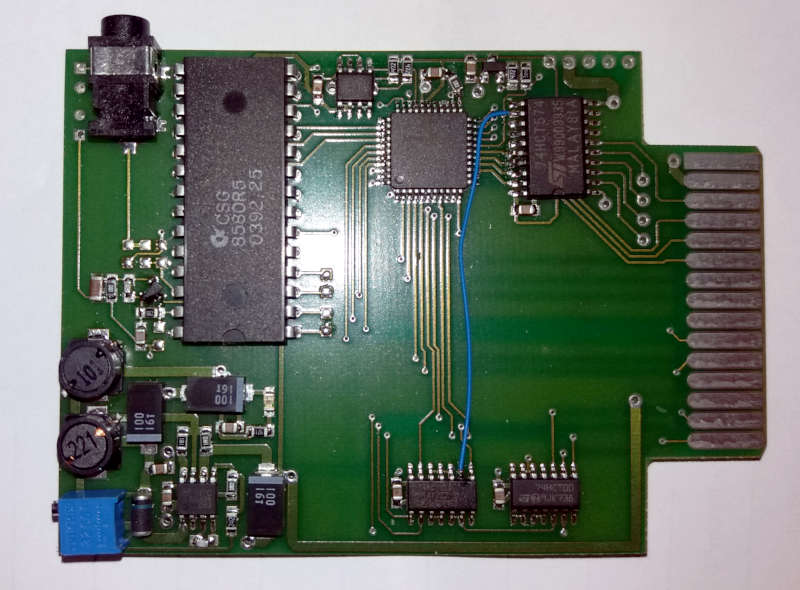
Pin... mój projekt nie jest projektem komercyjnym, wiem że to trwało za długo... nie liczę na jakieś kolosalne zainteresowanie i zdaje sobie sprawę z istniejących i powstających alternatyw, jednak jak pisałem wyżej... chodzi o to aby doprowadzić do końca coś czemu czas poświęciło trochę więcej osób niż ja... niech to będzie forma podziękowania z mojej strony dla tych którzy brali w tym udział. Dla mnie to była czysta radocha... mieć oryginalnego SID-a w formie carta, który gra z lepszą jakością niż SID znajdujący się w C64 ;-) (mniejsze szumy, większa dynamika, szersze pasmo). Dałoby się z tego wycisnąć jeszcze więcej soku, ale przy ilości wolnego czasu jaką obecnie dysponuje trwałoby to następne #n lat.
Jeżeli chodzi o emulowanego SID-a nigdy nie miałem ambicji aby coś takiego popełnić, uważałem że "analogowej" wersji nic nie dorówna, jednak ludzie pracujący nad tematem, szczególności w zakresie emulowania analogowego filtru, oraz to że dostępne są obecnie tak złożone i zaawansowane oraz tanie FPGA spowodowały że możliwe stało się w miarę wierne zbliżenie się do oryginału :)
Projekt toczył się przez lata i był jednym wielkim eksperymentem, powstało kilkanaście wersji na różnym hardware... każda miała z zanadrzu jakieś niespodzianki oraz dodatkowe możliwości... pewnie przyjdzie czas aby to wszystko opublikować, ale obecnie nie jest to możliwe ze względu coś co można nazwać "prozą życia", niestety są sprawy ważniejsze które mocno ograniczają moje możliwości działania i dokończenie wszystkich tych pomysłów z przed lat...
Jednak jak pisałem wyżej, patrząc na to co się dzieje dookoła i na świecie doszedłem do wniosku że dzielenie się wiedzą, doświadczeniem czy pomysłami jest wręcz moim obowiązkiem, dlatego jak pisałem wszystko to co tam siedzi w szufladzie sukcesywnie będzie opublikowane jako open-source, open-hardware i dostępne publicznie (pewnie via repozytoria na github). Na wszystko przyjdzie czas. Przyznam że długo biłem się z myślami czy to ma sens, jednak uznałem że może kiedyś coś komuś z tego się przyda w jakimś celu. A dodatkowo ludzie tacy jak np. tOri którzy dzielą się swoimi projektami przekonali mnie że warto tak robić.
Nie uważam swoich projektów za jakieś wybitne dzieła, wręcz przeciwnie... ale może znajdą się ludzie którzy dzięki moim "wypocinom" będą mogli czegoś się nauczyć i jakoś z tego skorzystać, i może dzięki temu powstanie w przyszłości coś nowego, przecież możliwości są nieograniczone... w dodatku uważam że wiedza która nie zostanie udostępniona i ginie gdzieś w odmętach komercji czy zapomnianych szufladach to naprawdę zmarnowany potencjał.
Hej!
Kiedyś słyszałem SwinSID-a... nie chcę ujmować nic autorowi projektu, kawał porządnej roboty... jednak moim zdaniem brzmienie tego rozwiązania jest mocno odmienne od oryginału. Nie chce być zrozumiany, bo zrobienie tego na AVR to i tak kawał pracy i pełen szacun dla autora rozwiązania, jednak ten projekt robiłem i projektowałem tak aby włożyć w niego oryginalne SID-y i aby poziom szumów oraz jakość sygnału na wyjściu była możliwie najlepsza. Nie posiadam niestety SwinSID-a i nie wiem czy to będzie działać z tym cart-em, jednak taktowanie SID-ów w tym cartcie jest identyczne jak w przypadku C64, SID-y chodzą dokładnie w takiej samej konfiguracji jak przypadku C64 (PAL lub NTSC). Więc nie powinno być z tym problemu.
Nie wiem czy jest w naszym małym świadku aż takie zainteresowanie tym rozwiązaniem które prezentuje, bo należy przyznać że to raczej bardzo niszowy projekt... i właściwie chciałem aby siedział w nim tylko i wyłącznie oryginalny SID, ale zdając sobie sprawę że może nastąpić problem z dostępnością tych układów w późniejszych latach będzie można pomyśleć o rozwiązaniu opartym o emulację. Zresztą Duddie proponuje swoje "zintegrowane" rozwiązanie, więc sądzę że ten projekt należy zostawić tak jak jest.
A jeżeli chodzi o emulację SID-a to kiedyś trafiłem na ten projekt: http://dzi.n.cz/8bit/armsid/index_en.php
Nie słyszałem jeszcze jak gra, ale jeżeli będzie dostępny ponownie do kupienia to zamierzam go kupić i przetestować.
ps1) Dely... ja pamiętam co obiecywałem i cały czas jesteś na liście osób która otrzyma w/w cart.
Jeżeli chodzi o cenę to pisałem na samym końcu pierwszego posta. Cena 130zł bez układów SID. Na kiedy? PCB gotowe, obudowy docięte... miała być nowa naklejka ale na 90% zostanie ta którą widać na zdjęciu, więc sądzę że w ciągu 2 tygodni będzie wszystko skręcone i gotowe do wysyłki dla zainteresowanych tematem osób.
atari.area forum » Posty przez seban
Wygenerowano w 0.098 sekund, wykonano 19 zapytań